TR34 2003 3rd Edition Appendix C Defined Movement Floor Classifications
In defined movement (DM) areas, Material Handling Equipment (MHE) travel along fixed paths.
Defined movement areas are usually associated with high-level storage racking with very narrow aisles (VNA) in warehouses.
This section of TR34 2003 3rd Edition Appendix C, Table C1 provides guidance on controlling surface regularity in defined movement areas which takes into consideration the relationship between the front axle and read axle of the Material Handling Equipment (MHE).
Features Measured
Property A – Transverse permissible elevational difference in mm between the centres of the front load wheels of the MHE.
Property B – Transverse permissible change in elevational difference (Rate of Change) for each 300mm of forward travel of the MHE.
Property C – Longitudinal permissible elevational difference in mm between the front and rear axle of the MHE.
Property D – Longitudinal permissible change in elevational difference (Rate of Change) for each 300mm of forward travel of the MHE.
Properties A, B, C and D are measured using Dabros Digital Floor Profiler, which can produce produces continuous or semi-continuous readings every 50mm with accuracy of 0.1mm. The interval between the readings can easily be adjusted to client’s requirements (for example, we can take readings every 10mm – 1000mm), however measurements taken every 50mm are sufficient enough to provide true profile of the path of the MHE.
Permissible limits on Properties A, B, C and D are shown in table below;
Table C1: Permissible limits on Properties A, B, C and D in defined movement areas.
| Floor classification | MHE lift height | Property A per 1m of axle length (mm) | Property AMHE (mm) | Property B Transverse RoC (mm) | Property C per 1m of axle length (mm) | Property D Longitudinal RoC (mm) |
95% limit | 95% limit | 95% limit | 95% limit | 95% limit | ||
DM 1 | Over 13m | 1.3 | 1.3 x T | 0.75 x Property AMHE | 1.1 x Property A x L | 1.3 |
DM 2 | 8m – 13m | 2.0 | 2.0 x T | 0.75 x Property AMHE | 1.1 x Property A x L | 2.0 |
DM 3 | Up to 8m | 2.5 | 2.5 x T | 0.75 x Property AMHE | 1.1 x Property A x L | 2.5 |
T – (Transverse) distance in “m” between the centres of the front load wheels of the MHE.
L – (Longitudinal) distance in “m” between the front load wheels and the rear axle of the MHE.
Existing practice in the control of surface regularity of floors is to expect up to 5% of exceptional measurements to exceed any of the Property limit by up to a maximum of 1.5 times its value when measured after initial construction and before any remedial grinding or filling is carried out. This assumes that the measurements have a normal distribution of values.
To reflect above, the table below was created to show the 100% limit for any of the required classification.
Floor classification | MHE lift height | Property A per 1m of axle length (mm) | Property AMHE (mm) | Property B Transverse RoC (mm) | Property C per 1m of axle length (mm) | Property D Longitudinal RoC (mm) |
100% limit | 100% limit | 100% limit | 100% limit | 100% limit | ||
DM 1 | Over 13m | 1.3 x 1.5 | 1.3 x 1.5 x T | 0.75 x Property AMHE | 1.1 x Property A x L | 1.3 x 1.5 |
DM 2 | 8m – 13m | 2.0 x 1.5 | 2.0 x 1.5 x T | 0.75 x Property AMHE | 1.1 x Property A x L | 2.0 x 1.5 |
DM 3 | Up to 8m | 2.5 x 1.5 | 2.5 x 1.5 x T | 0.75 x Property AMHE | 1.1 x Property A x L | 2.5 x 1.5 |
T – (Transverse) distance in “m” between the centres of the front load wheels of the MHE.
L – (Longitudinal) distance in “m” between the front load wheels and the rear axle of the MHE.
Limits Explained
1. No more than 5% of all the measurements for Property A, Property B, Property C and Property D in each individual aisle surveyed exceeds the 95% limit of the required classification;
Example:
Classification required = DM 2
Transverse = 1300mm
Longitudinal = 1800mm
a) 95% of all Property A measurements recorded must have values of max. 2.6mm (1.3 x 2.0) or less in order to comply with that classification.
b) 95% of all Property B measurements recorded must have values of max. 1.95mm (0.75 x 2.6) or less in order to comply with that classification.
c) 95% of all Property C measurements recorded must have values of max. 3.96mm (1.1 x 2.0 x 1.8) or less in order to comply with that classification.
d) 95% of all Property D measurements recorded must have values of max. 2.0mm or less in order to comply with that classification.
2. None of all the measurements for Property A, Property B, Property C and Property D in each individual aisle surveyed exceeds the 100% limit of the required classification;
a) 100% of all Property A measurements recorded must have values of max. 3.9mm (2.0 x 1.5 x 1.3) or less in order to comply with that classification.
b) 100% of all Property B measurements recorded must have values of max. 2.93mm (0.75 x 3.9) or less in order to comply with that classification.
c) 100% of all Property C measurements recorded must have values of max. 5.94mm (1.1 x 2.0 x 1.5 x 1.8) or less in order to comply with that classification.
d) 100% of all Property D measurements recorded must have values of max. 3.0mm (2.0 x 1.5) or less in order to comply with that classification.
TR34 2003 3rd Edition (Table 4.3) Defined Movement Floor Classifications
This section of TR34 2003 3rd Edition Table 4.3 provides guidance on controlling surface regularity in defined movement areas which takes into consideration only measurements that are recorded in the front wheel tracks of the Material Handling Equipment (MHE).
It does take into account the relationship between the front axle and read axle of the MHE. To measure this, an alternative method is given in TR34 2003 3rd Edition Appendix C, Table C1.
Features Measured
Property I – the elevational difference in mm between two points 300 mm apart. This feature is measured parallel to the direction of travel of the MHE.
Property II – the change in elevational difference between two consecutive measurements of Property I (points 300mm apart) over 600mm. This feature is measured parallel to the direction of travel of the MHE.
Property III – The elevational difference in mm between the centres of the front load wheels of materials handling equipment.
Properties I, II and III are measured using Dabros Digital Floor Profiler, which can produce produces continuous or semi-continuous readings every 50mm with accuracy of 0.1mm. The interval between the readings can easily be adjusted to client’s requirements (for example, we can take readings every 10mm – 1000mm), however measurements taken every 50mm are sufficient enough to provide true profile of the path of the MHE.

Table 4.3: Permissible limits on Properties I, II and III in defined-movement areas.
Floor classification | MHE lift height | Property I (mm) | Property II (mm) | Property III (mm) | |||||
Wheel track up to 1.5 m | Wheel track over 1.5 m | ||||||||
95% | 100% | 95% | 100% | 95% | 100% | 95% | 100% | ||
Superflat (SF) | Over 13 m | 0.75 | 1.0 | 1.0 | 1.5 | 1.5 | 2.5 | 2.0 | 3.0 |
Category 1 | 8–13 m | 1.5 | 2.5 | 2.5 | 3.5 | 2.5 | 3.5 | 3.0 | 4.5 |
Category 2 | Up to 8 m | 2.5 | 4.0 | 3.25 | 5.0 | 3.5 | 5.0 | 4.0 | 6.0 |
Limits explained
Each of the properties (Property I, Property II and Property III) have 95% and 100% limits.
In order for the floor to comply with any required classification following criteria have to be met:
1. No more than 5% of all measurements for each individual aisle exceeds the 95% limit of the required classification;
Example:
Classification required = Category 1
a) 95% of all Property I measurements recorded must have values of max. 1.5mm or less in order to comply with that classification.
b) 95% of all Property II measurements recorded must have values of max. 2.5mm or less in order to comply with that classification.
c) 95% of all Property III measurements recorded (for wheel track up to 1.5m) must have values of max. 2.5mm or less in order to comply with that classification.
2. None of all measurements for Property 1, Property II and Property IIII in aisle surveyed exceeds the 100% limit of the required classification;
a) 100% of all Property I measurements recorded must have values of max. 2.5mm or less in order to comply with that classification.
b) 100% of all Property II measurements recorded must have values of max. 3.5mm or less in order to comply with that classification.
c) 100% of all Property III measurements recorded (for wheel track up to 1.5m) must have values of max. 3.5mm or less in order to comply with that classification.
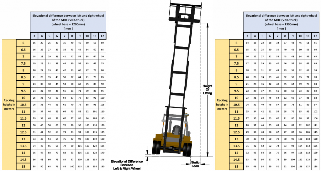
Static Lean
Below is an example of how truck lean increases with lifting height.
This is based on the truck with rigid mast, however due to the engineering tolerances in the mast and the dynamic forces when the VNA truck is in motion, values in the table could increase by up to 3 times.