VDMA – What is it?
In September 2010 VDMA introduced a guideline “Floors for use with VNA Trucks” which was a slightly amended version of the FEM Guidance note rejected by BITA Working Group in July 2010. Their decision was that the FEM 4.007 guidance note should be completely removed from the table and further validation was required. Shortly after that the FEM Working Group 4 was closed. However there is still push for it by some organisations.
In September 2010 VDMA introduced a guideline “Floors for use with VNA Trucks” which was a slightly amended version of the FEM Guidance note rejected by BITA Working Group in July 2010. Their decision was that the FEM 4.007 guidance note should be completely removed from the table and further validation was required. Shortly after that the FEM Working Group 4 was closed. However there is still push for it by some organisations.
VDMA device – what does it measure?
The principle of the VDMA survey is quite simple. The device used to measure VDMA (short wavelength) is 100mm long (from wheel centres) and measures the curvature of the floor in the middle of the distance, at 50mm. The indentation (positive or negative) recorded by the VDMA device is then multiplied by 2. Simply we could say that the VDMA device is a 100mm straight edge to check floor indentations at its centre with accuracy of 0.01mm.
VDMA device – how accurate is it?
The VDMA requirements state that all measurements must be taken with an accuracy of 0.01mm. It all sound great, but… it is impossible to read that accurate. Obviously the measurements could be taken to 0.01mm or even 0.001mm, but it does not necessarily mean that the value recorded reflects the TRUE profile of the floor. This is for number of reasons;
1. Tolerances allowed by the VDMA Guidelines;
a) Total runout tolerance for each axle is 0.05mm
b) Concentricity tolerance of all axles of 0.01mm
c) Parallelism tolerance of 0.05mm
2. Every ball bearings have their axial play,
3. Any dust, debris have also its thickness,
VDMA – Common issues and problems
Over the last few years DABROS Floor Surveys Ltd was involved not only in floor flatness surveys (including VDMA) and floor testing, but we were also involved in VDMA grinding which requires a lot of skills and knowledge. We have tested thousands of meters of defined movement areas for compliance with VDMA Fx,avg numbers and found few interesting and troubling aspects of the VDMA specification.
One of the issues is that we have noticed is that the floor MUST be perfectly clear from any dust and debris. Even few grains of sand/debris along the surveyed path generate errors which have big impact on the final flatness results.
Also the device’s measuring wheels are made of metal. As it travels down the aisle it generates vibrations caused by the moving device, which also generate errors.
DABROS Floor Surveys Ltd have noticed that it is basically impossible to find a “flat line” (which represents a perfectly flat floor) on the actual survey results graph. This is when we decided to look at what could cause these errors after disregarding two issues mentioned above)
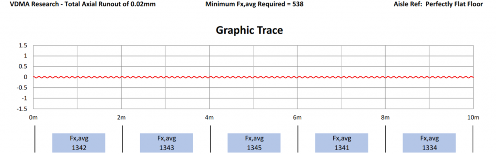
DABROS Floor Surveys Ltd have carried out 4 simulations of the VDMA survey on perfectly flat surface. The simulation disregarded ball bearings axial play, concentricity tolerance error and parallelism tolerance error, dust, debris etc. This means that these possible sources of errors did not have negative/positive impact on the results. Basically the VDMA device was tested in laboratory like conditions and was constructed PERFECTLY with one exception. The only source of error was generated by the wheel axles (total runout tolerance allows up to 0.05mm play for each of the axle).
We have gathered results for total runout of each individual axle of 0.02mm, 0.03mm, 0.04mm and at the maximum permissible limit of 0.05mm. Racking height was set to 15.5m, therefore required Fx,avg=538.
Two outer axles were set with the runout facing up, and middle axle was set with the runout facing down. Another words, the graphs below show the worst case scenario, when axles can produce worse results.
VDMA – Looking at the Fx,avg numbers
Also it can be seen that there is a massive “jump” in overall Fx,avg number depending on its built accuracy;
For VDMA device with runout tolerance of 0.02mm the Fx,avg is on average let’s say 1340.
JUMP DOWN OF 445
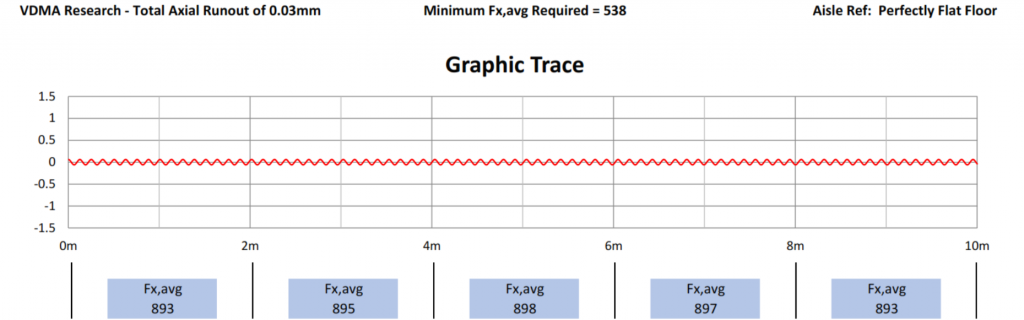
For VDMA device with runout tolerance of 0.03mm the Fx,avg is on average let’s say 895.
JUMP DOWN OF 223
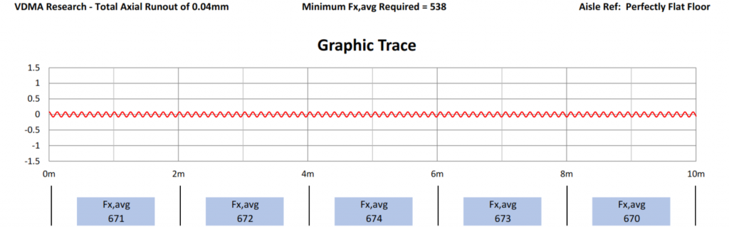
For VDMA device with runout tolerance of 0.04mm the Fx,avg is on average let’s say 672.
JUMP DOWN OF 135
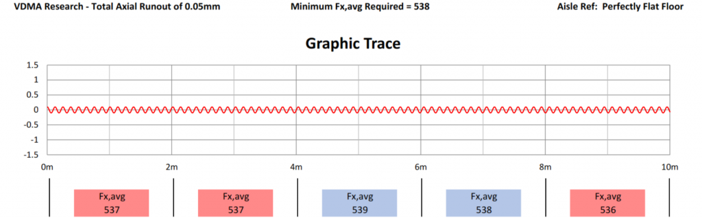
For VDMA device with runout tolerance of 0.05mm the Fx,avg is on average let’s say 537.
VDMA – Conclusion
As we can see from the results above, especially for the device with the total runout of 0.05mm for each axle, the device is unsuitable to carry out VDMA surveys for racking of more than 15.5m high, despite the fact the measuring device was built to a required tolerances. Also a perfectly flat floor is not flat according to the survey results. Obviously if we set the wheels runouts to be in the same position the results would be fine. Trouble is that by doing so there would not be repeatability in the results which is the CRUCIAL part of any type of flatness survey. We just do not have it with VDMA.
The results above also show, that even minimal floor curvature of a few hundredths of a millimetre combined with errors generated by the measuring device makes the VDMA specification useless to test flatness of the floor. This specification could only find its use in laboratory and on a perfectly clean floor which hardly (or ever) are found in warehouses, where dust, debris, stickers etc. located within the forklift wheel path would have massive impact on VDMA Fx,avg results.
Moreover, if we applied to this scenario concentricity error of 0.01mm the device would not be suitable to survey floors with the racking 12m high. That is obviously for the perfectly flat floor. If we add to the scenario minimal floor curvature we might never achieve the results that are required by the VDMA specification and will end up looking for a needle in a hay stack.
VDMA – VDMA – Final words
As we can see from above examples the rate of change in Fx,avg numbers is not linear. This means that the Fx,avg numbers very rapidly decrease with every 0.01mm change in floor curvature.
For the actual deviations of the floor of 0.03mm-0.05mm over 100mm distance the measuring device would produce results that will make any floor unsuitable for the racking height exceeding 6m. For comparison, paper thickness is normally around 0.09mm-0.1mm.
The wheels of the forklift trucks are made of polyurethane and any floor deviations of 0.05mm would easily be compensated by the wheels.
Based on above we ask a simple question.
DO YOU NEED YOUR FLOOR TO BE VDMA COMPLAINT?